Optical Torque Meter
I have a flashlight with a laser pointer, useful for torturing cats! (Don’t ask!)
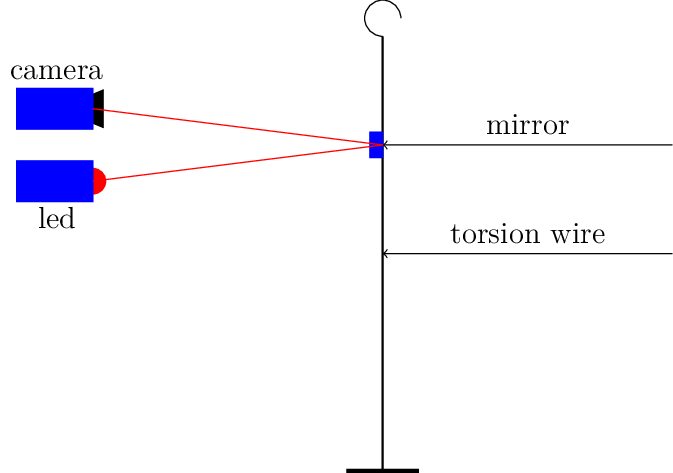
What I thought about was gluing a small mirror on the torsion wire and shining a light, maybe not a laser, at that mirror as it twists. The light beam would move across a flat surface of some kind and we could look at that instead of a rotating dial/ Again, image processing could be used to read the “meter. Not only would this be easy to construct, but it would be very inexpensive, especially if we just use an LED for the light source. The big question is will this be accurate enough?
The only way to tell is to build something and try it out!.
Raw Materials
Building this torque meter is going to be very simple. All I need is a chunk of wire like that used on most common torque meters, a small chunk of mirror and an LED.
Mirrors
Of course, it is bad luck to break a mirror, so my first task is to find a small piece of mirror. Fortunately, there are people in this world who build things like disco globes, and they have tons of suitable mirrors. A quick search in my local Hobby Lobby turned up a sheet of mirror tiles measuring 3/16” square for a few dollars per sheet.
One problem solved.
LED
I have tons of these, since I used then for student lab projects. You need a simple 330 ohm resistor to hook one of these up to a microcontroller.
Wire
My local hobby shop turned up this, along with a couple of DuBro wheel collars used to keep wheels from sliding off of wire landing gear. I will glue the mirror to tone of these to allow it to be moved along the torsion wire.
Here is a sketch of the idea:
First Experiment
For my first experiment, I set up my Raspberry Pi and its camera to make sure all was running.
Next, I located an image processing library for the Pi,
Adjusting the mirror
Obviously, I cannot let the mirror spin around in a complete circle if I plan on imaging the light reflected off of the mirror. That means I need a shorter wire to limit the twist angle to something suitable for visual spotting. We will rely on the high pixel count on the camera to get a good number to use for torque calculations. The wheel collar will allow for minor adjustments of the mirror position if needed.
The software presented earlier will provide a way to set up the required wire length.
Calibration
Once all of this is set up, we need to calibrate the meter so we can get reasonable data from it. We could just rely on calculations as a start, but wire manufacturing procedures and differences in the materials will result in errors. A better way is to use a known weight and connect that to the wire to produce a torque we can measure. That means we need to attach a calibration arm to the wire, just like the pointer used in traditional torque meters. We could just clamp this on using another wheel collar and avoid permanently attaching the arm. We will play with that to see if we can get good data.
Frame Rate
Once we have the software set up, we need to verify that we can spot the light on ghe viewing stage (just a piece of white paper will do). Once we can do that, we need to see how fast the light can move ans if we can measure its position with some accuracy. This does not need to be super fast, since we will not be winding or unwinding the motors very fast.
Meter Housing
If this works well enough for use, my plan is to design a 3D printable housing for the camera and the everything except the Pi to create a simple torque meter that can be used in the field (with some kind of display. I Pi Zero board an battery supply would make this a complete standalone device, and we could use Wifi to send data to a laptop if needed.
If we make this entire thing small enough, we could mount it on a swing arm for semi real flight testing og a moving propeller.
Graphical Display
If we want to go further, it would be simple to add a small screen and display the torque curves as they are recorded. That could show the hysterisus between winding and unwinding.